Topic: DMD0358

EIPMSG - Send EtherNet/IP Message
The Send EtherNet/IP Message (EIPMSG) instruction implements an Explicit Unconnected EtherNet/IP Client![]() An explicit unconnected message client initiates request/response oriented communications with other devices. Message rates and latency requirements are typically not too demanding. Examples of explicit message clients are HMI devices, programming tools, or PC-based applications that gather data from control devices. using the on-board Ethernet port of a Do-more CPU. An explicit message client initiates request / response oriented communications with EtherNet/IP servers. Message rates and latency requirements should not be too demanding. Examples of other explicit message servers you can talk to are barcode scanners, scales, drives, or other intelligent devices.
An explicit unconnected message client initiates request/response oriented communications with other devices. Message rates and latency requirements are typically not too demanding. Examples of explicit message clients are HMI devices, programming tools, or PC-based applications that gather data from control devices. using the on-board Ethernet port of a Do-more CPU. An explicit message client initiates request / response oriented communications with EtherNet/IP servers. Message rates and latency requirements should not be too demanding. Examples of other explicit message servers you can talk to are barcode scanners, scales, drives, or other intelligent devices.
EtherNet/IP uses the Common Industrial Protocol (CIP)![]() The Common Industrial Protocol (CIP) is a media independent, connection-based, object-oriented protocol designed for automation applications. It encompasses a comprehensive set of communication services for automation applications: control, safety, synchronization, motion, configuration and information. It allows users to integrate these applications with enterprise-level Ethernet networks and the Internet., a strictly object-oriented protocol, at the upper layers. Each CIP object has attributes (data), services (commands) and behaviors (reactions to events). In the CIP Protocol, every network device represents itself as a series of objects. Each object is simply a grouping of the related data values in a device. Application Objects allow the user to organize the data that are specific to a particular kind of device. These objects define the data encapsulated by the device. They are specific to the device type and function.
The Common Industrial Protocol (CIP) is a media independent, connection-based, object-oriented protocol designed for automation applications. It encompasses a comprehensive set of communication services for automation applications: control, safety, synchronization, motion, configuration and information. It allows users to integrate these applications with enterprise-level Ethernet networks and the Internet., a strictly object-oriented protocol, at the upper layers. Each CIP object has attributes (data), services (commands) and behaviors (reactions to events). In the CIP Protocol, every network device represents itself as a series of objects. Each object is simply a grouping of the related data values in a device. Application Objects allow the user to organize the data that are specific to a particular kind of device. These objects define the data encapsulated by the device. They are specific to the device type and function.
These application layer objects are predefined for a large number of common device types. The same type of CIP devices must contain the same series of application objects. The series of application objects for a particular device type is known as the device profile. Objects not found in the profile for a device class are termed Vendor Specific. These objects are included by the vendor as additional features of the device. The CIP protocol provides access to these vendor extension objects in exactly the same way as either application or required objects. The Send EtherNet/IP Message instruction gains access to these regular pieces of data from the network to the device through an Object (or Class) Number, an Instance Number (Instances are the way of organizing the same kind of data ,e.g., sharing same attributes ), and optionally an Attribute Number.
Element References:
Note: Use the F9 key or click the 'three dot box' at the right edge of the parameter field to open the Default Element Selection Tool (the Element Picker or the Element Browser) or use the Down-Arrow key (Auto-Complete) on any parameter field to see a complete list of the memory locations that are valid for that parameter of the instruction.
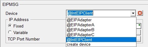
Device selects which EtherNet/IP Client devices to use to send the message. This instruction can use either EtherNet/IP Explicit Message Client devices or EtherNet/IP Implicit Scanner devices.
Click the drop-down box and select one of the preconfigured EtherNet/IP Explicit Message Client devices or one of the EtherNet/IP Implicit Scanner devices. The default selection is the built-in EtherNet/IP Explicit Message Client named @IntEIPClient.
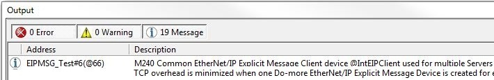
Note: If you will be communicating to more than one EtherNet/IP Servers (Servers with different IP Addresses), we recommend that a separate EtherNet/IP Explicit Message Client device be created for each of the EtherNet/IP Servers. Doing this will minimized the TCP overhead required to manage connections to multiple EtherNet/IP Servers. Any time you use the same EtherNet/IP Client Device for multiple IP Addresses you will see Info Message M240 similar to the following in the Output Window:
Click the drop-down box and select one of the preconfigured EtherNet/IP Implicit Scanner devices. Doing so will retrieve the IP Address and Port Number from the selected device and use that information in this instruction. The IP Address and Port Number values will be displayed within parentheses in the instruction.
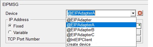
Click the drop-down box and select create device will open the following dialog where you select the type of EtherNet/IP client device to create:
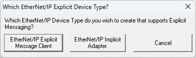
Selecting one of the client device types will open the appropriate Create New Device dialog in the System Configuration.
IP Address specifies the IP Address of the EtherNet/IP Server (Slave) to send the message to. If thel Device is an EtherNet/IP Implicit Adapter, the IP Address from the selected device is used and cannot be set in the instruction.
- Select Fixed IP Address if the
IP Address of the EtherNet/IP Server (Slave) is a fixed (static) IP Address. IP addresses are canonically represented in
dot-decimal notation, consisting of four decimal numbers, each ranging
from 0 to 255, separated by dots. This can be any valid IP Address on
the same local network as the Do-more CPU or the ECOM module.
- Select Variable IP Address if the IP Address resides in a memory location in the PLC. This allows the IP Address to be changed at runtime. This can be any readable DWord numeric location. Each octet of the IP Address is stored in one byte of the Variable Address location. In the example below the Initialize Data instruction will use the :UB operator to place the 4 octet values of IP Address 192.168.26.71 into the 4 Bytes of the DWord location D0 in the proper order.
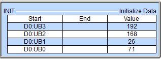
Note: the 'IP Address' format selection in a Data View can be used to see the IP Address stored in the DWord location in the traditional dot-decimal notation (000.000.000.000).
TCP Port Number is the port number of the EtherNet/IP Server (Slave) to send the message to. The default value of 44818 is typically the correct port number for EtherNet/IP protocol. This can be any constant value between 0 and 65535, or any readable numeric location containing a value in that range. If the Device is an EtherNet/IP Implicit Adapter, the Port Number from the selected device is used and cannot be set in the instruction.
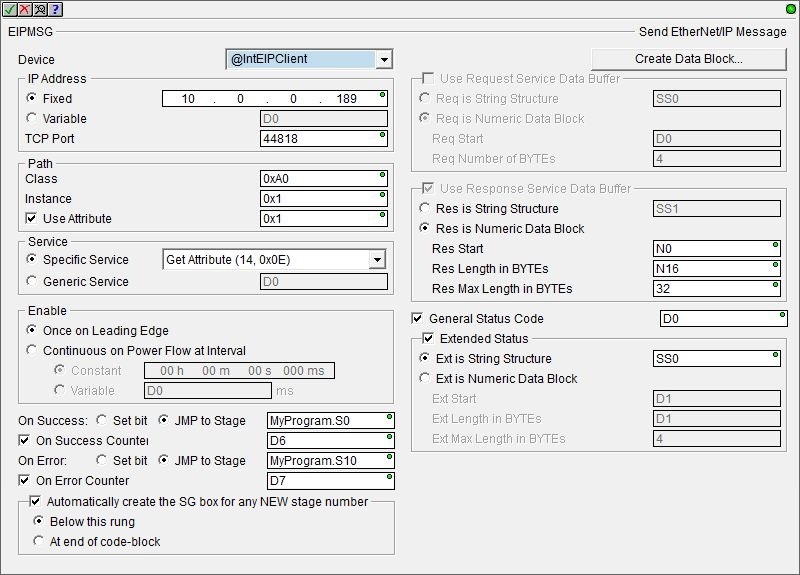
Path specifies the parameters for the request. The specific values needed for the fields will be provided by the manufacturer of the EtherNet/IP server that you are talking to.
Class is the Class ID value as defined by the EtherNet/IP Server. This can be any positive integer value or any readable numeric location. It is also possible to address the Class itself versus a specific Object Instance within the Class. This is accomplished by utilizing the Instance ID value zero (0). CIP reserves the Instance ID value zero (0) to indicate a reference to the Class versus a specific Instance within the Class.
Instance is the Instance ID value as defined by the EtherNet/IP Server. This can be any positive integer value or any readable numeric location.
Enable the Use Attribute option to specify the Attribute value as defined by the EtherNet/IP Server. This can be any positive integer value or any readable numeric location. The Attribute entry isn’t specific to Class Attributes or Instance Attribute:
To address a Class Attribute enter the Class number in the Class field, enter 0 in the Instance field, and the desired Attribute in the Attribute field.
To address the Instance Attributes of a Class enter the Class number in the Class field, enter the Instance number in the Instance field, and the desired Attribute in the Attribute field.
Service specifies the operation to perform on the set of objects. Choose from the following list of predefined Services, or select Generic and enter the Service number.
Select one of the Specific Service Requests below:
Get Single Attribute (14, 0x0E) to request a single attribute.
Set Single Attribute (16, 0x10) to write a single attribute.
Get All Attributes (1, 0x01) to request all of the attributes.
Set All Attributes (2, 0x02) to write to all of the attributes.
Or select Generic to specify a Service that is NOT one of the predefined Service Requests. This can be any constant integer value or any readable numeric location.
Enable selects how this instruction will operate. Select from one of the following:
-
Select the Once on Leading Edge to have this instruction run to completion exactly one time. Typically, this instruction will take more than one controller scan to complete. Configured this way the instruction is considered Edge Triggered
 Each time the input logic transitions from OFF to ON this instruction will execute. With each execution, this instruction will run to completion even if the input logic transitions to OFF before the instruction completes..
 -
Select the Continuous on Power Flow at Interval option to have this instruction run as long as the instruction has power flow. After the instruction has run to completion, if it still has power flow the instruction will remain enabled and will wait the specified amount of time before running again. The following options specify how much time (in milliseconds) to wait before the instruction is set to run again. A value of 0ms means the instruction will re-run immediately.
The On Success and On Error parameters specify what action to perform when this instruction completes. You do not have to use the same type of selection for both On Success and On Error.
If the Set Bit selection is used for either On Success or On Error, the specified BIT location will be SET OFF when the instruction is first enabled and will remain OFF until the instruction completes. Once complete, the appropriate Success or Error bit location ON. The specified Bit location is enabled with a SET (Latch) operation meaning that it will remain ON even if the input logic for the instruction goes OFF.
If the JMP to Stage selection is used for either On Success or On Error the target Stage must be in the same Program code-block as this instruction, you cannot specify a target Stage that exists in a different Program code-block. When the operation finishes, the target Stage will be enabled the same way as a standalone Jump to Stage (JMP) instruction would do it. The JMP to Stage option will only be available if this instruction is placed in a Program code-block.
On Success selects which of the following actions to perform if the operation is successful:
- Enable SET Bit then specify any writable bit location.
- Enable JMP to Stage then specify any
Stage number from S0 to S127 in the current Program code-block.
On Error selects which of
the following actions to perform if the operation is unsuccessful:
- Enable SET Bit then specify writable bit location.
- Enable JMP to Stage then specify any Stage number from S0 to S127 in the current Program code-block.
If either the On Success or On Error selections are set to JMP to Stage, Automatically create the SG box for any NEW stage number will be enabled which will automatically create any target stage that does not already exist.
- Below this rung will create the new target stage on a new rung following this instruction.
- At end of code-block will create the new target stage as the last rung of this Program.
On Error Counter - enable this option and select a DWord location to store the total number of times the EIPMSG instruction failed to complete. This can be any DWord location.
If an appropriate data block does not already exist, or if you want to create an additional data block for use in this instruction, then click the Create Data Block button button to open the following dialog where you can create a new data block of the required type.
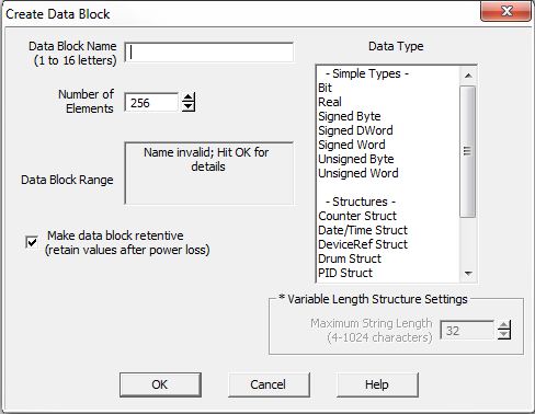
Data Block Name (1 to 16 letters) : block names must be unique, and consist of 1 to 16 characters (A-Z, a-z; no numbers, no spaces).
Number of Elements specifies the number of bytes in the data block. The data blocks must be created on a DWord (4-byte) boundary. The maximum number of Bytes that can be received from a single packet is 1024.
Unsigned Byte Block Range displays the first and last element of the block that will be created based on the current entries for Data Block Name and Number of Elements.
The Data Type determines the type of data that the block will contain.
Make Data Block Retentive (retain values after power loss) means that a data block marked as retentive will hold its state through a power cycle or a Program-to-Run mode transition. The status of memory NOT marked as retentive will be cleared at power up and during a Program-to-Run mode transition.
The Use Request Service Data Buffer selection will be automatically enabled when any Set Attribute service is selected and automatically disabled when any Get Attribute service is selected. This buffer can be enabled any time the Generic Service is selected.
- Select Req is String Structure if the data for the Set Attribute service or any Generic service is contained in a String, then enter the String element to use. This can be any
of the system-defined Short Strings, or system-defined Long Strings, or
any of the user-defined Strings. The maximum length of the String to send is 500 bytes.
- Select Req is Numeric Data Block if the data for the Set Attribute service or any Generic service is contained in a numeric memory block. The maximum size of the data block that can be sent in a single service request 500 bytes (250 Words, 125 DWords, 125 Reals).
Req Start is the first element of the memory block that is the data for the Set Attribute or Generic service.
Req Number of Bytes is the number of consecutive BYTEs of data for the Set Attribute or Generic service (Words = 2 Bytes, DWord = 4 Bytes, Real = 4 Bytes).
The Use Response Service Data Buffer selection will be automatically enabled when any Get Attribute service or any Generic service is selected and automatically disabled when any Set Attribute service is selected. This buffer can be enabled any time the Generic Service is selected.
- Select Res is String Structure to store the data from the Get Attribute service or any Generic service in a String, then enter the String element to use. This can be any
of the system-defined Short Strings, or system-defined Long Strings, or
any of the user-defined Strings. The maximum length of the String that could potentially be received is 500 bytes, so make sure the String can handle the maximum response for the desired service.
- Select Res is Numeric Data Block to store the data from the Get service or any Generic service in a numeric memory block. The maximum size of the data block that can be read in a single service request 500 bytes (250 Words, 125 DWords, 125 Reals).
Res Start is the first element in the numeric data block to store the data that was returned by the Get Attribute or Generic service. This can be any writable numeric location.
Res Length in BYTEs is a memory location to store the actual number of Bytes of data that was returned by the Get Attribute or Generic service. This can be any writable numeric location.
Res Max Length in BYTEs is the maximum number of BYTEs of the returned data to retain to store in the data block. This can be any positive integer constant between 1 and 500 or any readable numeric location.
Note: this value should be a multiple of the number of BYTEs in a single element in the numeric memory block. For example, if the memory block consists of DWords or Reals, this value should be a multiple of 4, as there are 4 BYTEs per DWord or Real.
Enable the General Status Code option to store the value returned from the EtherNet/IP Server in response to processing the Service Request; enter the numeric location to store the value. This can be any writable numeric location. This value could indicate success or be an error code. Consult the documentation for the EtherNet/IP Server for information on how to interpret General Status Code values.
Enable the Extended Status option to store any extended status value returned from the EtherNet/IP Server in response to processing the Service Request.
- Select Ext is String Structure to store the extended status information in a String, then enter the destination String element. This can be any
of the system-defined Short Strings, or system-defined Long Strings, or
any of the user-defined Strings.
- Select Ext is Numeric Data Block to store the Extended Status data in a numeric data block.
Ext Start is the first element in the numeric data block to store the Extended Status data. This can be any writable numeric location.
Ext Length in BYTEs is a memory location to store the actual number of Bytes of Extended Status data. This can be any writable numeric location.
Ext Max Length in BYTEs is the maximum number of BYTEs of Extended Status data to store in the data block. This can be any positive integer constant between 1 and 500, or any readable numeric location. This value should be a multiple of the number of BYTEs in a single element in the numeric memory block. For example, if the memory block consists of DWords or Reals, this value should be a multiple of 4, as there are 4 BYTEs per DWord or Real.
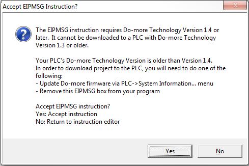
Note: if you add an EIPMSG instruction to your project, when you close the EIPMSG instruction editor you will see the following message box noting that this instruction requires Do-more Technology Version 1.4 or later. This means that you can add the instruction to the offline project, but you cannot download a project contain this instruction to a Do-more PLC that is running a firmware version older than v1.4.
If you are editing the project offline you will see this message box:
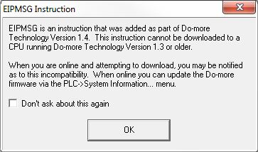
If you are editing the project online you will see this message box:
Status Display:
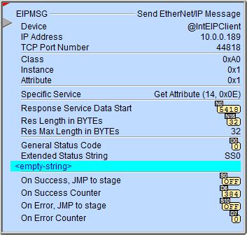
The red triangle in the upper left corner of the status display indicates this is a Fully Asynchronous instruction.
See Also:
EIPMSG - Send EtherNet/IP Message
DLRX - DirectLOGIC Network Read
DLWX - DirectLOGIC Network Write
PEERLINK - Share Data w / PLCs
PUBLISH - Translate from Do-more
SUBSCRIB - Translate to Do-more
Related Topics:CPU Configuration -> EtherNet/IP Server / Adapter Configuration
I/O Configuration -> EtherNet/IP Scanner Configuration
|
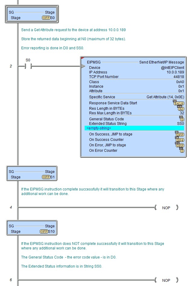
Example: